Welcome Offer: 15% Off
Your Favourite Products, Delivered to Your Door | One Marketplace for All Your Everyday Needs
Shop & Earn Coins


Secure Payments
SSL encrypted checkout
Fast Delivery
Delivered Across the UK
Trusted Shopping
Simple & Secure
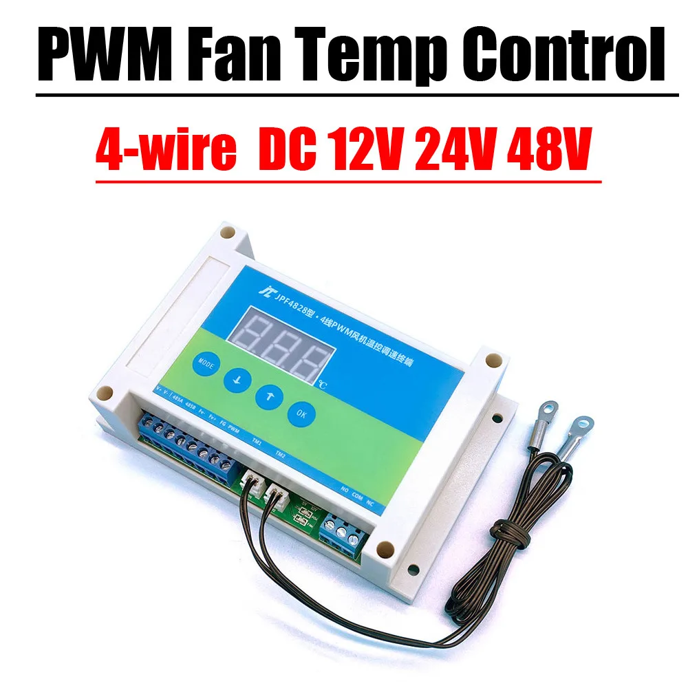
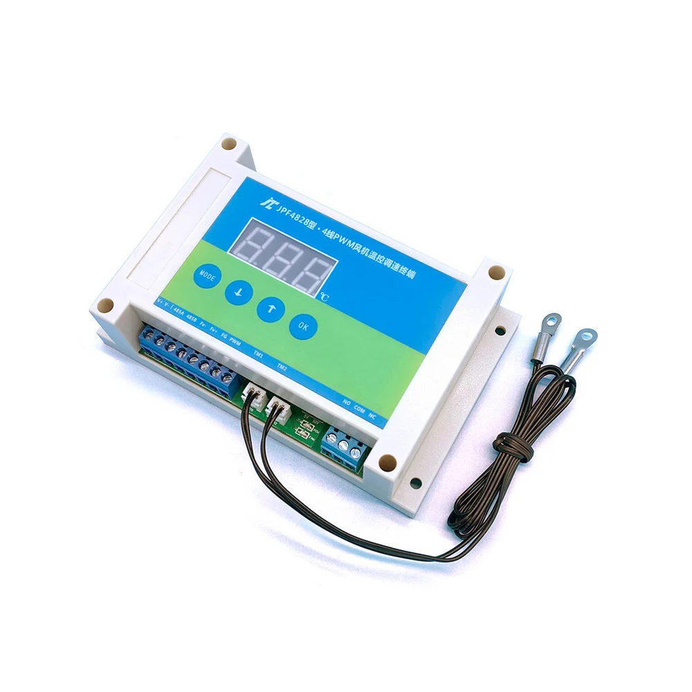
4-wire DC fan PWM temperature control speed regulation air volume speed automatic temperature control EC fan 0-10V speed regulation mute noise reduction
Functional Overview:
The fan speed controller adopts ARM chip as the core component, industrial-grade quality, real-time temperature measurement with dual temperature probes,
The speed controller controls the fan speed (air volume) through the detected temperature; the fan speed is proportional to the temperature: the higher the temperature, the fan speed
The faster the temperature, the slower the fan speed. When the temperature is lower than the set start temperature, the fan can be stopped or maintained at a minimum
Speed; automatically balance the temperature and fan speed, truly achieve the effect of on-demand heat dissipation, energy saving and noise reduction, and prolong the life of the fan.
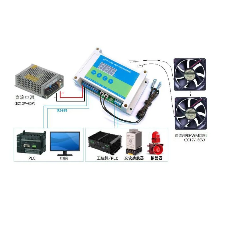
The governor supports fan speed detection, fault alarm, RS485 communication and other functions, RS485 follows the modbus-rtu protocol
2. Product performance/technical parameters:
1. Industrial-grade solution, using ARM series microcontroller as the main control chip, with stable performance
2. Wide voltage design, support 12V/24V/48V four-wire PWM fan/motor direct access, maximum drive current 12A
3. With LED indication, visual indication of the working state of the governor
4. Power supply anti-reverse connection protection design, power supply reverse connection will not damage the device
5. Fan start, full speed temperature can be set freely, support minimum speed and fan shutdown two working modes
6. Supports fan speed detection, fan fault detection, and comes with dry contact (relay) signal output
7. Support RS485 serial communication, standard modbus-Rtu protocol,
8. RS485 serial port TVS anti-surge design, serial port parameters are 9600bps, 8, N, 1
9. Dual sensor temperature measurement, supports up to 8 fans connected at the same time
10. PWM output frequency 25Khz, amplitude 5V/10V configurable
11. Temperature measurement range: -10~99°C, temperature measurement accuracy: ±1°C
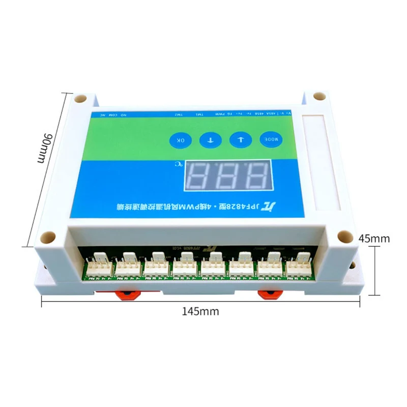
12. Support two installation methods: guide rail and screw fixing
13. Working temperature: -30~80°
5. Basic instructions for use
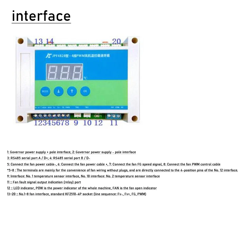
5.1 Connect the wiring according to the interface instructions
5.2 After the power supply is normal, the POW light on the main board will light up, and the governor starts to recognize the temperature detected by the two temperature sensors.
Whoever has a higher temperature will use whose temperature value to adjust the speed of the fan. Taking the factory default temperature range of the governor as an example,
The factory default temperature range of the governor is L=30°C, H=50°C, when the current temperature detected by one of the temperature sensors
When the temperature is greater than or equal to 30°C, the governor adjusts the speed of the fan in a linear proportion.
When the temperature is ≥50°C, the fan becomes full speed. When the temperature drops to ≤27°C (L-3), the governor keeps the fan at the minimum speed
speed/or shut down the fan
6. About the use of fan fault signal indicating relay
A low-power relay (dry contact) is integrated in the governor, which is mainly used to indicate the abnormal stop of the fan, which can be used as an indication
The signal is connected to the digital input port of the PLC/IPC, and can also be used as a switch to directly control other low-power equipment
Relay parameters: AC250V/DC30V, maximum load current 3A
When the fan is normal, the relay is disconnected (COM and NO are disconnected, and NC is connected),
When it is detected that the fan stops abnormally, the relay will be closed (COM and NO are connected, and NC is disconnected).
7. About the selection of PWM control signal voltage amplitude
The governor supports PWM signal output of two voltages, 5V/10V,
Under normal circumstances, the domestic mainstream 4-wire fan can use the PWM signal of 5V voltage, but some imported or special fan
The speed controller may need 10V PWM signal to adjust the speed; the user can adjust the PWM voltage of the speed controller according to the actual situation.
Chengdu Jingzhicheng Electronic Technology Co., Ltd. www.jzcet.com Tel:028-66570969/18227618314
8. Digital panel operation instructions
The digital panel displays the current temperature in real time (displays the highest temperature value),
With 4 buttons, all parameters of the governor can be set through the buttons
In the standby state, press the ↑ key to manually switch to display the temperature values detected by the two temperature sensors.
In the standby state, press the MODE key to enter the configuration/switch parameter item, press the ↕ key to adjust the value during configuration, and press the OK key to confirm
*When setting parameters, each time you set a parameter (change the parameter value), you must press the OK key once to confirm, and then set the next item
Lxx : Fan start temperature Set the fan start (lower limit) temperature value / setting range: 1~99°C
Hxx : Fan full speed temperature Set the fan full speed (upper limit) temperature value / setting range: 1~99°C, the value of H must be greater than the value of L
Axx : MODBUS address Set the address of the 485 serial port MODBUS protocol of the governor/setting range: 1~254
Pxx working mode
Set the working mode of the governor
When the temperature is lower than the set start temperature -3°C, use this parameter to set the governor to be
Controls whether the fan is turned off or maintained at the minimum (20%) speed)
Setting range: 00/01; 01 means to maintain the minimum speed, 00 means to turn off the fan
Number of Fxx fans
Set the number of fans connected to the governor
The value of this parameter must be consistent with the number of fans actually connected, and the
When the fan is installed, the fans must be connected in the order of FAN1~FAN8. If the setting is
01, then when the fan is actually connected, the fan must be connected to the fan1 port, if the setting is
02, then when the fan is actually connected, the two fans must be connected to fan1 and fan2, so that
By analogy, if it is not connected according to this requirement, it will cause an error in the fan fault detection function.
Setting range: 0~8 (when set to 0, it means that the fan fault detection function is not enabled)
*If the fan fault detection function is not used, this parameter can be ignored
8. Digital panel operation instructions
The digital panel displays the current temperature in real time (displays the highest temperature value),
With 4 buttons, all parameters of the governor can be set through the buttons
In the standby state, press the ↑ key to manually switch to display the temperature values detected by the two temperature sensors.
In the standby state, press the MODE key to enter the configuration/switch parameter item, press the ↕ key to adjust the value during configuration, and press the OK key to confirm
*When setting parameters, each time you set a parameter (change the parameter value), you must press the OK key once to confirm, and then set the next item.
Digital display code Parameter definition Parameter description
Lxx fan start temperature
Set the fan start (lower limit) temperature value
Setting range: 1~99°C
Hxx fan full speed temperature
Sets the fan's full speed (upper limit) temperature value
Setting range: 1~99°C, the value of H must be greater than the value of L
Axx MODBUS address
Set the address of the 485 serial port MODBUS protocol of the governor
Setting range: 1~254
Pxx working mode
Set the working mode of the governor
When the temperature is lower than the set start temperature -3°C, use this parameter to set the governor to be
Controls whether the fan is turned off or maintained at the minimum (20%) speed)
Setting range: 00/01; 01 means to maintain the minimum speed, 00 means to turn off the fan
Number of Fxx fans
Set the number of fans connected to the governor
The value of this parameter must be consistent with the number of fans actually connected, and the
When the fan is installed, the fans must be connected in the order of FAN1~FAN8. If the setting is
01, then when the fan is actually connected, the fan must be connected to the fan1 port, if the setting is
02, then when the fan is actually connected, the two fans must be connected to fan1 and fan2, so that
By analogy, if it is not connected according to this requirement, it will cause an error in the fan fault detection function.
Setting range: 0~8 (when set to 0, it means that the fan fault detection function is not enabled)
*If the fan fault detection function is not used, this parameter can be ignored
*Take setting the start and full speed temperature of the fan as an example
In the standby state, the panel displays the current temperature value, press the MODE key once, the digital tube displays Lxx, L represents the startup temperature,
xx represents the currently set temperature value,
Press the up and down keys to adjust the parameter value. After the adjustment is completed, press the ok key to confirm and return to the standby interface.
In the standby state, press the MODE button twice, the digital tube displays Hxx, H represents the full speed temperature, and xx represents the currently set temperature
value, press the up and down keys to adjust the parameter value, after the adjustment is completed, press the ok key to confirm
After the setting is completed, the governor will automatically control the speed of the fan according to the newly set temperature parameters.
The settings of other parameters are similar to the above steps.

Total
£35.02